Timer Circuit With Relay

Timer circuit with relay
Upon application of input voltage, the time delay relay is ready to accept a trigger. When the trigger is applied, the time delay (t1) begins. At the end of the time delay (t1), the output is energized. When the trigger is removed, the output contacts remain energized for the time delay (t2).
What is a relay timer?
Timer Relays A Timer Relay is a combination of an electromechanical output relay and a control circuit. The contacts will open or close before or after a pre-selected, timed interval.
What is the difference between a timer relay and a relay?
Relays are switches that open and close circuits electromechanically or electronically. Timers control timing in applications where functions need to be delayed or loads need to be maintained for a predetermined period.
How do you delay a timer on a circuit?
A button 100 ohms resistor 470 kilohm resistor for his 7 micro farad capacitor. 12 volt relay and a
How many types of timer relays are there?
ON-delay timers and OFF-delay timers are two common types of time delay relays and solid state timers.
What are the four 4 modes of time delay relays?
Time delay relays are built in these four basic modes of contact operation:
- 1: Normally-open, timed-closed.
- 2: Normally-open, timed-open. ...
- 3: Normally-closed, timed-open. ...
- 4: Normally-closed, timed-closed.
Where are timing relay used?
Timing Relays are used extensively in industrial applications, HVAC systems and building services to provide time-delayed switching. For example to start a motor, control an electrical load, or simply automate an action. They play a vital role for targeted logic needs.
How does the relay work?
Relays are electric switches that use electromagnetism to convert small electrical stimuli into larger currents. These conversions occur when electrical inputs activate electromagnets to either form or break existing circuits.
What is the most commonly used timing relay?
On- and off-delay timers represent the most typical time delay relay timers in use. Other types include interval-on-operate, flasher, and repeat cycle timers.
What is the purpose of a time delay relay?
Time delay relays are like normal relays however introduce a timing element in order to intentionally delay when the relay either turns on (energises) or turns off (de-energises). Used typically to control various types of equipment throughout many types of industries.
What are the four functions of a relay?
As a control element, relays have the following functions:
- Expanding control range.
- Amplification. ...
- Integrated signal. ...
- Automatic control, remote control, and monitoring.
Which type of relay is used as time delay relays?
One-shot timers are a time delay relay used to activate a circuit after a set amount of time has passed. They are also called single shot timers, single shot interval timers, and single pulse timers. One-shot timers are activated by power. As soon as power is applied, the contacts move to a different position.
What is 555 on a relay?
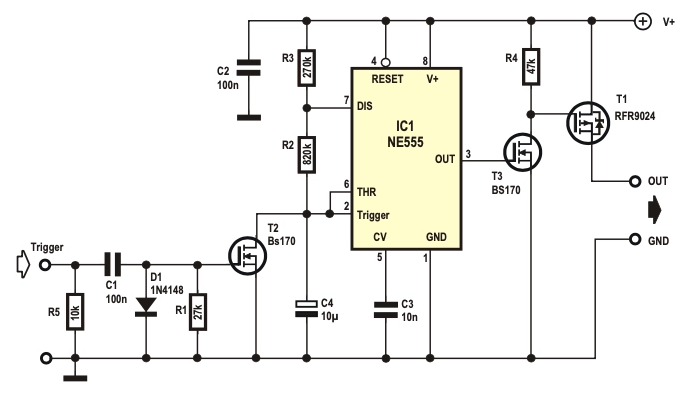
The 555 timer is configured as a Monostable Multivibrator. The output load is driven by the relay switch which is in turn controlled by the timer circuit. Since the project only involves assembling a simple circuit by following the schematic, it will only take an hour to make.
Can you put a timer on a breaker?
If you mount it to the side of the breaker panel with a tiny piece of conduit you can probably just disconnect the wire from the breaker and run it to the timer without having to extend it. Then just run a new neutral and ground in to the timer and a new hot wire from the breaker to the timer.
What is transistor timer circuit?
A timer switch or timer circuit is a timer to control any electronic switches or circuits by a timing mechanism. Here, the timer is a very simple circuit, working by using just one or a pair of transistors. this circuit serves its purpose of time delays operation of a device.
How do I test a timer relay?
Burden Test
- Adjust the timer with high time delay for example: 2 minutes.
- Energize the relay with 125V and measure the dc current.
- Note down the current before timer operates.
- After 2 minutes relay will pick up. Note down the current after operation.
- Calculate the relay power (W) = 125v x measured current.
What are the types of PLC timers?
There are three main types of PLC timers: – The on-delay timer, – The off-delay timer, – The retentive on-delay timer.
What are the two basic classification of timers?
Timers are classified into two types as follows: On-delay relay. Off-delay relay.
What is application of timer to?
A timer is a specialized type of clock which is used to measure time intervals. A timer that counts from zero upwards for measuring time elapsed is often called a stopwatch. It is a device that counts down from a specified time interval and used to generate a time delay, for example, an hourglass is a timer.
What is on delay timer in PLC?
On-Delay Timer (TON) It is used when an action is to begin a specified time after the input becomes true. Consider an example wherein a certain step in the manufacturing process is to begin 30 seconds after a signal is received from a limit switch. The 30 seconds delay is the ON-delay timer's preset value.
14 Timer circuit with relay Images
How does NE555 timer circuit work Datasheet Pinout ElecCircuit

Arduino adjustable timer Hobby Electronics Electronics Projects

Switchable Monostable 555 Timer Circuit at Four Rotary Switch Position

555 Timer Circuit With Variable OnOff Times EEWeb Community

How does NE555 timer circuit works Datasheet Pinout ElecCircuit

Construa circuitos de transistor simples Circuit projects Electronic
555 Watchdog timer with power disconnect nel 2020

555 Timer Circuits Circuit Electronic engineering Circuit diagram

LED Chaser Circuit with 555 timer Chaser Circuit electronic LED

Schematic diagram of storage latch comparator and relay driver circuit

Pin on Timer circuits

Timer Testing Wiring Diagram Earth Bondhon Digital Timer High

Simple Delay Timer Circuits Explained Basic Electronic Circuits
Post a Comment for "Timer Circuit With Relay"