Rc High Pass Filter Transfer Function

Rc high pass filter transfer function
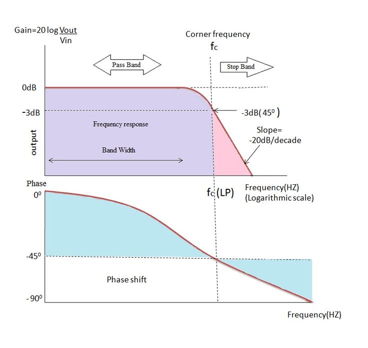
The High-Pass Transfer Function The magnitude response at ωO will be 3 dB below the maximum magnitude response; with a passive filter, the maximum magnitude response is unity, in which case the value at ωO is –3 dB. The absolute value of the circuit's phase shift at ωO will be 45°.
What is the transfer function of RC low-pass filter?
T(s)=K1+(sωO) This transfer function is a mathematical description of the frequency-domain behavior of a first-order low-pass filter.
What is function of high pass RC circuit?
1. A high pass filter or HPF, is the exact opposite of the LPF circuit. It attenuates or rejects all low frequency signals and passes only high frequency signals above ωc. In practical filters, pass and stop bands are not clearly defined, |H(jω)| varies.
What is the order of RC filter transfer function?
X c = 1 s C. Applying voltage division rule, we get the transfer function as: V 0 V i = 1 s C 1 s C + R. V 0 V i = 1 1 + s R C.
What is transfer function of RC circuit?
The transfer function H(s) of a circuit is defined as: H(s) = The transfer function of a circuit = Transform of the output Transform of the input = Phasor of the output Phasor of the input .
What is the transfer function of a filter?
A filter transfer function that contains complete quadratic equations in both the numerator and denominator and provides the basis for implementing high-pass, low-pass, and single-frequency notch characteristics as well as band-reject realizations.
What is high pass and low pass filter?
Low pass filter: Low pass filter is the type of frequency domain filter that is used for smoothing the image. It attenuates the high frequency components and preserves the low frequency components. High pass filter: High pass filter is the type of frequency domain filter that is used for sharpening the image.
How is high-pass filter calculated?
The cut-off frequency, corner frequency or -3dB point of a high pass filter can be found using the standard formula of: ƒc = 1/(2πRC). The phase angle of the resulting output signal at ƒc is +45o.
What is RL high-pass filter?
A high pass RL filter is a filter composed of a resistor and inductor which passes through high-frequency signals. To build a high pass RL filter, the inductor is placed in parallel to the power source signals entering the circuit, as shown below in the following circuit: The above circuit is an RL high pass filter.
What are the advantages of high pass filter?
Whenever there is a small signal is present, an active High pass Filter is used to increase the amplification factor, which also increases the amplitude of those small signals. Due to very high input impedance, active high pass filters can transfer efficient signals without any loss in any preceding circuit.
How capacitor works in high pass filter?
Capacitive high-pass filters insert a capacitor in series with the load; inductive high-pass filters insert a resistor in series and an inductor in parallel with the load. The former filter design tries to “block” the unwanted frequency signal while the latter tries to short it out.
What is first order high pass filter?
A first-order (single-pole) Active High Pass Filter as its name implies, attenuates low frequencies and passes high frequency signals. It consists simply of a passive filter section followed by a non-inverting operational amplifier.
What is second order high pass filter?
Second-Order Active High Pass Filter: The second-order filters have two reactive components; in this case, it is capacitors. These second-order filters are preferred over the first order due to its high roll-off rate. It has the roll-off rate of 40dB/Decade or 12dB/octave providing more steeper gain slope.
What is high pass and low-pass RC circuit?
An RC high-pass filter, also known as an RC Differentiator, works oppositely. The input signal applies directly to the capacitor with a resistor in parallel with the output, as shown above. By arranging components in this way, high-frequency signals can pass, while the capacitor blocks any frequencies that are too low.
What is RC formula?
As a result, a series RC circuit's transient response is equivalent to 5 time constants. This transient response time, T, is expressed in seconds as τ= R.C, where R is the resistor value in ohms and C is the capacitor value in Farads.
How do you find the transfer function?
To find the transfer function, first take the Laplace Transform of the differential equation (with zero initial conditions). Recall that differentiation in the time domain is equivalent to multiplication by "s" in the Laplace domain. The transfer function is then the ratio of output to input and is often called H(s).
What is the meaning of a transfer function?
In engineering, a transfer function (also known as system function or network function) of a system, sub-system, or component is a mathematical function that theoretically models the system's output for each possible input. They are widely used in electronics and control systems.
Why transfer function is used?
The key advantage of transfer functions is that they allow engineers to use simple algebraic equations instead of complex differential equations for analyzing and designing systems.
How do you calculate transfer function in control systems?
The transfer function of a system is defined as the ratio of Laplace transform of output to the Laplace transform of input where all the initial conditions are zero. ... Transfer Function
- T(S) = Transfer function of the system.
- C(S) = output.
- R(S) = Reference output.
- G(S) = Gain.
How do I know if my filter is high pass or low pass?
If a filter passes low frequencies and blocks high frequencies, it is called a low-pass filter. If it blocks low frequencies and passes high frequencies, it is a high-pass filter.
12 Rc high pass filter transfer function Images
High Pass Filter Explained High pass Filters Inductors

Low Pass Filter Passive RC Filter Tutorial Tutorial Filters

Easily enhance portraits in Photoshop CC with our fantastic FREE

Pin on PCB Designs

Pin on Projects to Try

Active Low Pass Filter Circuit Design and Applications Circuit design

Helical Bandpass Filter Designer in 2023 Ham radio Filters Ham

Fig Band pass filter circuit using R L and C components Circuit

Photoshop CS5 Extended Another colour change excercise using Hue

Low and High Pass Filter circuit High pass Circuit diagram Circuit
Passive Low Pass RC Filters Filters Passive Electronics
Post a Comment for "Rc High Pass Filter Transfer Function"